Yesterday I had a solar system and storage battery installed into my house. As part of that, inspired by Jon Oxer’s great SuperHouse series, I had the electrician install some high current relays for me to control the hot water system.
My plan has two intended control options:
- with an automated timer.
- directly with my own code and controller.
The Timer
K3 is a Finder “Digital Astro Time Switch” with NFC connection support (12.81.8.230.0000).
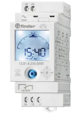
Once the timer is programmed with the location coordinates, it automatically calculates what time the sun should be up based on date. This means as the seasons change, the timer should automatically change when it activates to match the expected sunrise so the hot water system is fed solar power. I haven’t quite worked out how to convince it to do this, but time will tell 😄
The Circuit
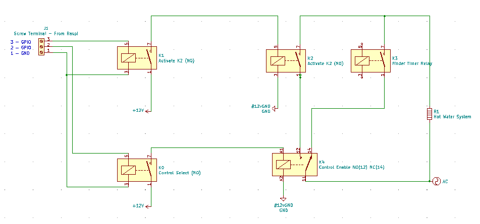
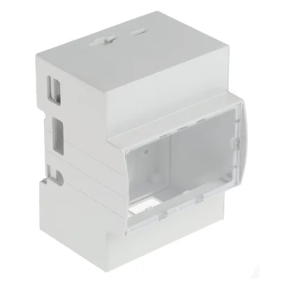
K0 and K1 are relay drivers on a Freetronics 4-Channel Relay Driver Module, connected to the GPIOs on a Raspberry Pi. The Pi is in an Italtronic Modulbox DIN Rail Case.
K4 is what I call the “control selection” relay - it’s a NO/NC relay where the NC pole connects to the timer, and the NO pole leads to K2, which will be controlled by my code. K2 has the NO pole connected to the hot water system.
There’s also a tertiary “force on” circuit breaker that allows me to power the hot water system on regardless of what the automation layer is doing - nobody likes cold showers due to computers. It’ll stay off most of the time, I hope :)
DC Power for the Raspberry Pi is coming from an RS-Components branded 5V DIN rail power supply, and the relays are driven by a 12V version. The original 12V one I ordered was the 70W version, but it’s waaaaay too deep compared to the 5V version and neither of them fit into the sub-board I got installed. 😒
Control logic
My home automation setup’s mainly run with a combination of Home Assistant and its inbuilt [Node-Red] instance. I’m still working out how to get it all working, but that’s for a future post.
| K4 | Timer | K2 | Result |
|---|---|---|---|
| Off | Off | N/A | Off |
| Off | On | N/A | On |
| On | N/A | Off | Off |
| On | N/A | On | On |
So it defaults to the timer, but I can take control.
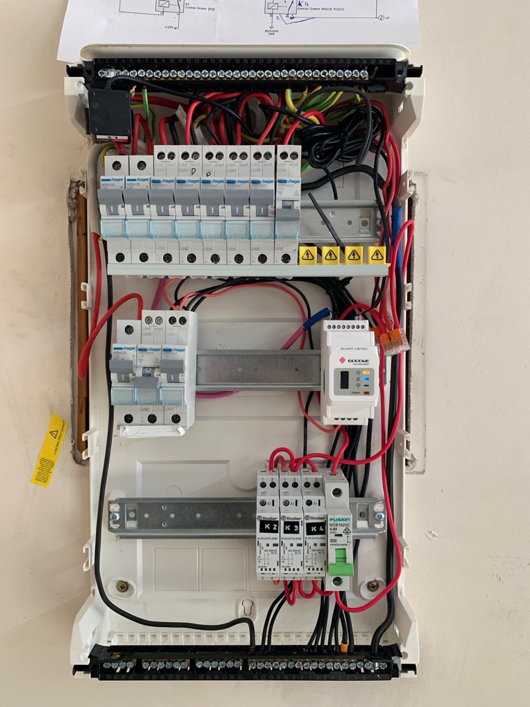
This is the internal breaker board in my garage, when the cover is off. There’s a few more things to go in, namely the 12V control side. Update to come later. 😄
Raspberry Pi Pins
| Pin | Colour | GPIO | Relay Pin | Action |
|---|---|---|---|---|
| 29 | Green | 5 | 3 | |
| 31 | Blue | 6 | 2 | Enable K2 |
| 32 | Yellow | 12 | 4 | |
| 33 | Purple | 13 | 1 | Enable K4 |